Performance
Since 1990, Quartzdyne has designed and manufactured the industry-standard resonating quartz pressure transducer for the downhole oil and gas industry. Our sensors are world-renowned for providing extremely accurate, low drift, and high resolution data in the most extreme conditions.

Accuracy
Quartzdyne downhole transducers offer accuracy of ±0.015% FS to 0.02% FS depending on the model. (The accuracy of the standard used in our calibrations, 0.01% of reading, must be added to these figures.) Quartzdyne’s accuracy specification includes all sources of error, including the effects of repeatability, linearity, and hysteresis. This is contrary to most transducer manufacturers’ practices, but we feel it is a better measure of performance. For example, a separate specifications for linearity and temperature sensitivity are meaningless, because the transducer is designed to be used with a digital correction for linearity and temperature sensitivity.
Each unit is supplied with the unique coefficients which allow pressure and temperature to be computed from the output signals. This figure shows the residual error (deviation from the polynomial fit) of a typical Quartzdyne downhole transducer. The test data used to compute the coefficients are supplied with each transducer.
Resolution of better than 0.01 psi with a one-second gatetime is typical. Counting frequency for infinite time will not provide infinite resolution: at some point, noise may limit useable information. Available resolution of Quartzdyne transducers can be 0.001 psi. We recommend gatetimes of 0.1 seconds or more.
The Series DS transducers offer 0.01% FS accuracy, over the laboratory temperature range of 0 to 40 °C, and 0.02% FS accuracy, over the field (outdoor) range from -40 °C to +85 °C.
Reliability
Quartzdyne utilizes two data sources to track product reliability: internal testing and customer returns/feedback. Internal tests are designed to test a specific element (crystal, circuit, bellows) over a range of operating conditions. This requires several customized tests, each optimized to probe the element in question for specific failure criteria. Customer returns provide valuable feedback, revealing which areas need the most improvement and where internal testing should be improved.
We maintain an extensive database containing measurements from all internal tests and customer returns. Continuous analysis of these data, and then focusing on the “weakest link” has led to significant improvements over the past twenty years. For Quartzdyne, continuous improvement lies in increasing the working life of each transducer.
Therefore, a thorough review of the field performance of Quartzdyne Pressure Transducers helps us chart our progress towards this goal. Publishing field reliability data, both the good and the bad, is rare in the oil and gas industry. We do it to establish customer confidence in our ongoing work of continuous improvement.
This Tech Notes provides additional reliability information on Quartzdyne products: Transducer Reliability Statistics (June 2020).
Stability
In early 1999, we began a program to quantify and improve the long-term stability (drift) performance of our pressure transducers. Since the rate of drift increases with temperature, we have focused our efforts on minimizing the drift at temperatures of 150 °C and higher. The quartz pressure crystal is responsible for most of the drift, while the quartz reference crystal makes a smaller contribution through the mixed pressure frequency.
We have conducted hundreds drift tests and found that Quartzdyne sensor drift can be predicted and compensated for using an algorithm. In contrast, piezoresistive sensor drift is unpredictable. Piezoresistive drift increases exponentially with increasing temperature.
Due to the complexity in manufacturing quartz pressure sensors, quartz transducers are more expensive than strain or piezoresistive gauges. With its long-term stability and accuracy, quartz retains its value over time through extended recalibration intervals. Thus, a tool using our quartz pressure transducer will remain in service for a longer period than a piezoresistive tool, earning more revenue for the service provider. Hence, we emphasize life-cycle costs with our customers, not initial costs.
Powered Life
Quartzdyne continuously tests it’s products in extreme environments including operating in high temperature conditions. In powered life, transducers are powered at temperatures above their rated or recommended operating temperatures and each component is monitored until failure. Based on the respective component being monitored, the test temperature is tailored to test that components life at the elevated temperature. Temperatures range from 150 °C to 250 °C. The report link has further details on the specific tests and failure data for various transducer components.

Transient
Quartzdyne downhole pressure transducers are designed to respond to very rapid changes in pressure. The problem to be solved by the transducer engineer is that large, rapid changes in pressure produce temperature changes (due the work required to compress fluids), this is commonly called “PV heating”.
Although the pressure sensor responds instantaneously to pressure, it cannot respond instantaneously to temperature. It does have some thermal mass. Quartzdyne includes both pressure and temperature sensors inside the transducer; matching the response of these sensors to both pressure and temperature events provides the rapid response to pressure steps and temperature ramps
Quartzdyne has designed the transducers for optimum performance in the downhole environment of simultaneously increasing pressure and temperature. Experimental results showing the response to extreme conditions are demonstrated in the article below.
Shock & Vibration
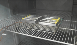
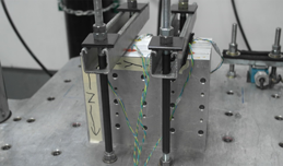
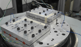
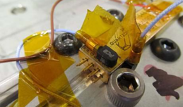
Each Quartzdyne transducer design has been qualified by environmental testing, thermal shock, random vibration, sine sweep, low-level shock, and drop shock. Quartdyne’s internal standards for these tests are detailed in the article below. Each transducer is not individually tested, due to the risk of latent damage, however, each design is periodically tested to re-certify the design. In addition, new product development, early on in the design process, and certain product improvements enlist HALT (Highly accelerated life test) and an internal Quartzdyne drop shock test to expose problems.
Environmental Testing of Quartzdyne Transducers and Circuits
The growing use of Quartzdyne transducers in logging-while-drilling has prompted laboratory vibration and shock testing at extreme levels to determine potential problem spots in the transducer design. These tests have led to significant changes in methods for fabricating and installing the transducers’ temperature and reference crystals.
Calibrations
To achieve the highest accuracy in sensors, calibration is a critical element. Calibration of a quartz transducer can stay valid for years, allowing downhole tools to spend less time being serviced and more time providing value in the field. When developing a re-calibration protocol, the best approach is to re-calibrate only the pressure transducers that demonstrate need for it. See the articles below for more details.
Quartzdyne Calibration information
Pressure:
• Pressure is generated with precision automatic and manual dead weight testers with 0.01% of reading accuracy.
• Sensor hysteresis is assessed by stepping up to full scale and then stepping down to ambient.
• Pressure drift is analyzed by full scale soaking both before and after calibration.
Temperature:
• All downhole pressure transducers are calibrated in stirred oil baths that are stable and uniform to 0.01 °C.
• Each pressure step causes PV heating or cooling, which requires waiting for the event to decay before readings are made.
• Sub-sea and surface units are calibrated in refrigerated ovens.
Our History
ChampionX has been serving customers for over a century. See our vast company history that dates back to the 1800’s.
Our Solutions
Discover all that ChampionX has to offer with our visual interactive tool.
Resource Library
Filter through our latest product literature to find case histories, product brochures, news, and more.
Why work with us
7,300+
Employees
60+
Countries
40+
Manufacturing Locations
400+
Scientists and Technologists


